Data flag
Required
Description
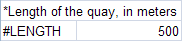
#LENGTH
Yes
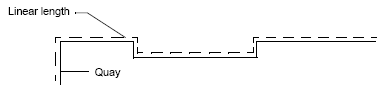
Identifies the length of the quay (in meters). All measurements should be taken in a linear way using the water’s edge from one end of the quay to the other, regardless of the quay’s shape.
The figure illustrates how the linear measurement follows the outline of the quay.
Example:
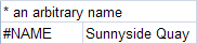
#NAME
Yes
Names the quay and determines the text that displays in the title bar of the Berth Schedule window.
Example:
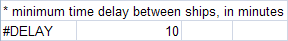
#DELAY
NO
Defines the minimum time delay between ships (in minutes) to allow for one ship to depart before the next ship arrives.
Example:
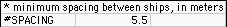
#SPACING
Yes
Defines the minimum spacing (in meters) between adjacent ships.
Enter the minimum length (in meters) of the gap in the quay where ships cannot cross boundaries. The minimum value is 0; the maximum value is 500.
Example:
#BERTH
Yes
Defines the linear to and from positions on the quay (in meters) and their respective names (arbitrary). This section also lets you specify, on a berth by berth basis, whether berth conflicts appear. See Display berth conflicts (on page 1).
This flag also includes these optional fields:
-
Ingress vertex
-
Egress vertex
-
Meter mark
-
Berth face to water
Vertices define where the container handling equipment (CHE) enters the area (ingress) and exits the area (egress). Vertices are numbered in the Yard Path Modeling scheme and defined in the berths.txt file using the #VERTEX data flags. The ingress and egress vertices are placed in the fourth and fifth column, respectively. They are only required if your site uses a Yard Path Model.
Meter mark records the meter marks of the berth. Use a negative number if meter marks decrease to the right.
Berth face to water
You can repeat the #BERTH data flag to accommodate as many berths as needed.
This data defines a general area, but multiple small vessels could occupy one large berth.
Example:

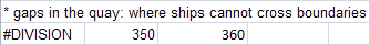
#DIVISION
NO
Identifies the gaps in the quay where ships cannot cross boundaries (in meters). For a quay without gaps, this data flag is not required.
If you do not want a vessel to straddle any specific area, you must define divisions using the #DIVISION data flag.
Example:
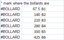
#BOLLARD
Yes
Marks the bollard positions (in meters) and names (arbitrary). A bollard is a line-securing device on the wharf around which mooring and berthing lines are fastened.
If your site uses a Yard Path Model, use the optional fifth and sixth columns to record the ingress and egress vertices. The vertices are numbered in the Yard Path Modeling scheme and defined using the #VERTEX data flags in this file. Vertices define where the container handling equipment (CHE) enters the area (ingress) and exits the area (egress).
You can repeat the #BOLLARD data flag to accommodate as many bollards as needed.
Example:
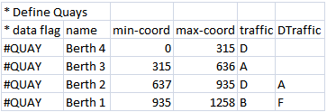
#QUAY
Yes, but only with Yard Path Modeling
Marks the quay name (arbitrary), the minimum and maximum position of the quay (in meters using the berth coordinate system), and the direction of traffic. In addition, you can configure whether XPS dynamically changes the direction of traffic according to the vessel berthing direction for each quay.
The traffic field defines the direction of traffic with one character for the container handling equipment operating in the area, as follows:
-
A (ascending): Traffic flows in the ascending direction of the logical coordinates of the block.
-
D (descending): Traffic flows in the descending direction of the logical coordinates of the block.
-
B (both): Traffic flows in both directions of the logical coordinates of the block.
The DTraffic field defines whether XPS dynamically changes traffic according to the vessel berthing direction, as follows:
-
A (aft): Traffic flows from the aft to the fore of the vessel.
-
F (fore): Traffic flows from the fore to the aft of the vessel.
-
Blank: Turns off this feature for this quay. In this case, the traffic is determined by the traffic field.
If you enter a value of A or F for the DTraffic field for a quay, the traffic direction for that quay is determined by the berth orientation (direction) of the visiting vessel regardless of any values in the traffic field. However, when there is no vessel visit, the traffic direction is determined by the traffic field for that quay or by the quay transfer zone block in the yard file (if you use the transfer approach to define the quay). The DTraffic setting applies for any timeframe.
You can repeat the #QUAY data flag to accommodate as many quays as needed.
Example:
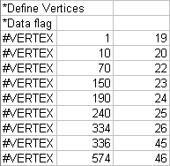
#VERTEX
Yes, but only with Yard Path Modeling
Marks the position of the vertex (in meters using the berth coordinate system) and vertex number (as used the in the Yard Path Modeling numbering scheme).
You can repeat the #VERTEX data flag to accommodate as many vertices as needed.
Example:
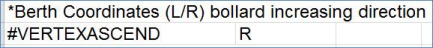
#VERTEXASCEND
Yes, but only with Yard Path Modeling
Indicates whether bollard positions increase to the left (L) or right (R) when you face the water. If this flag is not set properly, all bollard information will be miscalculated.
Example:
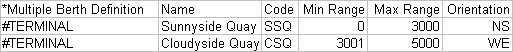
#TERMINAL
NO
Follows the #NAME data flag and defines a terminal which is really the yard. ABS requires at least one.
You can repeat the #TERMINAL data flag to accommodate as many terminals as needed. All terminals must range between 0 and the value defined in the #LENGTH data flag. Terminals cannot overlap because all berth locations must resolve to a unique terminal.
This data flag requires that you specify values in the following columns:
-
Name: An arbitrary title XPS uses in the title bar of the ABS window.
-
Code: A code of up to 5 alphanumeric characters. It should match the terminal codes already defined in N4 and in the XPS yard files. Both the yard file and the berths file use the Yard code, and the naming must be consistent.
-
Min Range: The starting point (real offset) of the terminal (specified in meters). This value ranges between 0 and the value set with the #LENGTH data flag. Define each terminal with a unique range because terminal ranges cannot overlap.
-
Max Range: The ending point (real offset) of the terminal (specified in meters). This value range between 0 and the value set with the #LENGTH data flag. Define each terminal with a unique range because terminal ranges cannot overlap.
-
Orientation: Must be either NS (north to south) or the default value (WE) west to east.
Example:
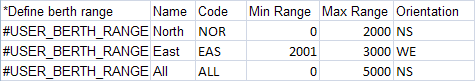
#USER_BERTH_RANGE
Yes
Follows the #TERMINAL data flag and defines a customizable berth range or a subsection of a berth.
You can repeat the #USER_BERTH_RANGE data flag to accommodate as many berth ranges as needed. The berth range can overlap terminals and must fall between 0 and the value defined in the #TERMINAL data flag.
This data flag requires that you specify values in the following columns:
-
Name: An arbitrary title that XPS uses in the title bar of the ABS window.
-
Code: A code of up to 5 alphanumeric characters. It should match the terminal codes already defined in N4 and XPS yard files. Both the yard file and the berths file use the Yard code, and the naming must be consistent.
-
Min Range: The starting point (real offset) of the terminal (specified in meters). This value range between 0 and the value set with the #LENGTH data flag.
-
Max Range: The ending point (real offset) of the terminal (specified in meters). This value range between 0 and the value set with the #LENGTH data flag.
-
Orientation: Must be either NS (north to south) or the default value (WE) west to east.
Example: